
Product system
Flare Boom Pilot Ignition System
Delivering the most reliable pilot ignition system for you
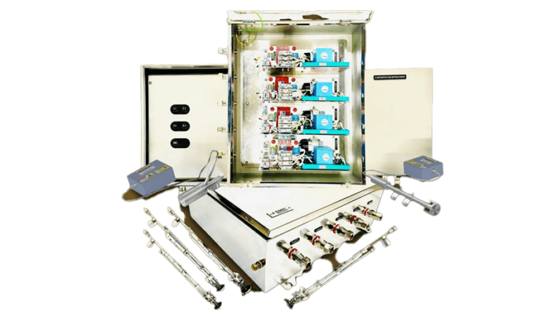
A flare ignition system must reliably deliver ignition energy from the control point to the pilot under the environmental and hazardous-area conditions of the installation. SMEC supports engineered ignition packages including ignition points, HEA cards/tips, HV cables, pilot interfaces, hazardous-area junction/control panels, field stations and commissioning.
01Overview
About the Flare Boom Pilot Ignition System
Standards and specifications
- Standard Energy
- 12 Joules
- Spark Rate Per Second
- > 5 Sparks
- Input Voltage
- 110 or 230 V AC, 50/60 Hz
- Duty Cycle
- 15 Mins On & 15 Mins Off (1:1)
- Maximum Current
- 5 Amps
01Why SMEC?
- High Energy Ignition
- Natural Draft Pilot
- Compact Design
- Cost Effective
- MOC SS316
- High Temperature Resistance Steel Braided Cables
- Explosion Proof
- Stainless Steel Panels
- Longer Life
- Easy Maintenance
- Insensitive to Moisture & Dirt Easy Retrofit
- Optional Flame Monitoring AC and DC Input
- Options Cable Length Up to 150 Meters
02Engineering detail
Engineering detail
Reliable Pilot Ignition Begins with the Entire Ignition Circuit
A flare pilot ignition package must be engineered around the pilot arrangement, ignition energy, cable routing, environmental exposure and safe operating procedure. SMEC's scope can include ignition controls, field junction boxes, high-voltage cables and status interfaces as specified.
Technical scope / product architecture
- Multiple ignition-point architecture as project-defined
- HEA cards/tips
- High-voltage ignition cables
- Pilot interfaces
- Ex-proof SS316 junction/control panels where specified
- Hazardous-area glands/terminals to approved project requirements
- Local pushbutton/field station
- FAT, installation and commissioning
What SMEC adds
Engineering, interface definition, panel/package build, software/configuration where applicable, FAT, site installation support, SAT/commissioning and lifecycle support.
How it works
Ignition path — An ignition control panel energises pilot ignition devices through specified cables, field junction boxes and ignition hardware.
Pilot arrangement — Pilot count, tip arrangement, distance and environmental exposure influence the ignition architecture.
Feedback — Flame proving or ignition status indication is specified separately from the act of generating a spark.
Field installation — HV insulation, earthing, Ex-rated equipment and safe test procedures are essential for offshore and process-area installations.
Key components
Ignition control panel. Panel layout, ingress protection, segregation, component selection and service clearance follow the installation environment, load schedule and maintenance requirements.
Ignition cards. The ignition cards is selected for the equipment, operating duty and site conditions.
Pilot igniters and tips. Pilot ignition depends on the complete circuit: ignition energy, electrodes, high-voltage cable condition, earthing and the site operating procedure.
High-voltage cable interfaces. The high-voltage cable interfaces is selected for the equipment, operating duty and site conditions.
Field junction boxes. The field junction boxes is selected for the equipment, operating duty and site conditions.
Pushbutton stations. The pushbutton stations is selected for the equipment, operating duty and site conditions.
Status feedback. The status feedback is selected for the equipment, operating duty and site conditions.
Hazardous-area equipment. The hazardous-area equipment is selected for the equipment, operating duty and site conditions.
Upgrades & retrofits
Replace ignition cards, HV cabling and field junction boxes as needed.
Add pilot points or local/remote initiation stations to an approved sequence.
Introduce flame status feedback where supported by the pilot arrangement.
Retrofit scope depends on existing OEM interfaces, component condition, available space, shutdown windows and the approval basis of any safety-related functions.
Applications
- Offshore platforms
- Well testing
- Production facilities
- Refineries
Testing & documentation
Relevant IEC, ISO, API, classification-society, hazardous-area or functional-safety requirements must be selected according to the specific system and installation. Where applicable, the project package may include electrical drawings, GA layouts, datasheets, I/O schedules, cause-and-effect, communication lists, inspection records, FAT/SAT procedures, calibration records and as-built documents. No unverified compliance certification is claimed here.
03More from the range
Other SMEC systems
Every system is built to the rig it serves and integrated with the rest of the installation.
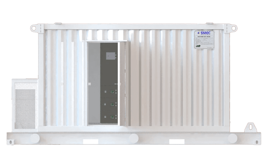 Power HousesPCR House | SCR House | VFD HouseKnow More
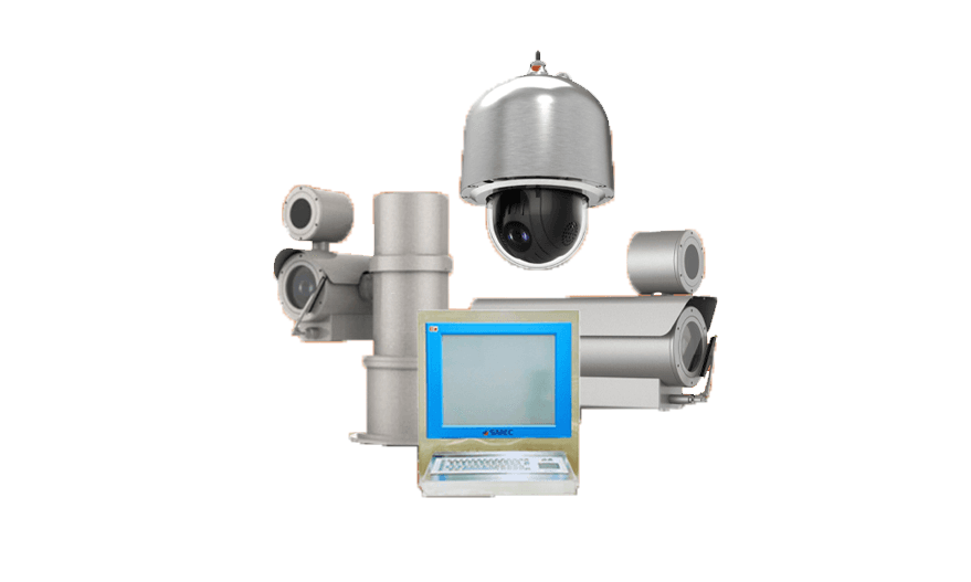 Advanced Perimeter Security SystemSecure Your Boundaries with SMEC's Advanced Perimeter Security System!Know More
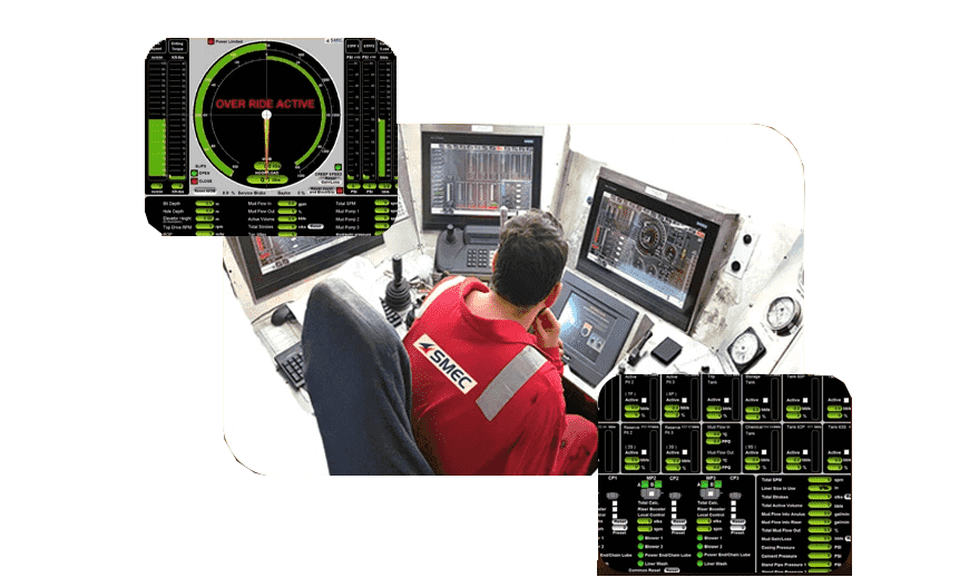 Drill Monitor SystemStay Alert, Stay Safe: Gas Watch Panel by SMECKnow More
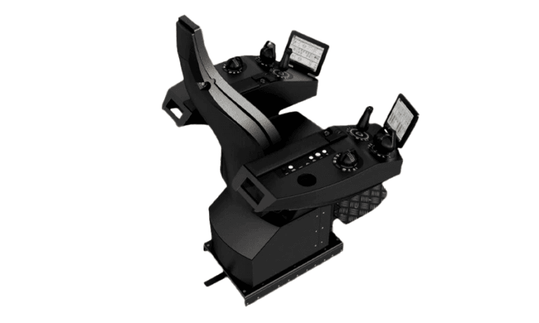 Integrated Drilling Control SystemElevate Your Drilling: Precision Meets Innovation with SMEC’s Integrated Control System!Know More
Common questions
Can Flare Pilot Ignition System be supplied for new build, retrofit or replacement?
The lifecycle route depends on the installed base, condition, interfaces, obsolescence and project requirements. SMEC can assess new-build, retrofit, repair or replacement scope where technically valid.
Can existing field wiring or interfaces be retained?
Possibly. Retention depends on survey findings, condition, ratings, compatibility, safety requirements, documentation and the cutover strategy.
What information is required for quotation?
Send the make/model or required specification, datasheets, drawings, ratings, interfaces, fault details where applicable, site location and required date or shutdown/mobilization window.
Can an old ignition panel be replaced while retaining pilot hardware?
Sometimes, after compatibility and condition checks.
Is flame detection included?
It can be specified as an interface or package element, but must be explicitly defined.
What should the RFQ include?
Pilot count, existing ignition arrangement, drawings, hazardous-area rating and site conditions.
Related pages
Send the requirement
Send the available drawings, specification, make and model, site and required date. An engineer reviews the scope and replies.