
Product system
Integrated Drilling Control System
Integrated with modern technology for seamless operations
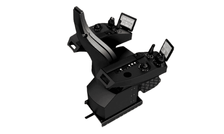
An Integrated Drilling Control System coordinates operator commands, machinery controls, drives, interlocks and selected rig package interfaces through a common control architecture. SMEC can engineer new systems or modernize legacy control layers while preserving required machinery and field interfaces.
01Overview
About the Integrated Drilling Control System
01Why SMEC?
- Cut down rig operation and maintenance costs
- Increases safety
- Centralized control
- Significant rig tasks Automation
- Improves response time and safety
- Simultaneous monitoring of multiple equipment
- Continuous power management
- Easy maintenance and troubleshooting
- Seamless control of rig & drill operations
- User-friendly interfaces and field-proven technology
- Provides comfortable, ergonomic work area
- Easy installation, commission, maintenance, support & repair
02Also featuring
- Advanced technology
- Interactive controls
- Multi-tool control cabinet
02Engineering detail
Engineering detail
One Driller Console. Coordinated Rig Control.
Integrated drilling control connects the operator, machinery controls and protective interlocks across the drilling package. The engineering challenge is not simply bringing equipment onto one screen: it is defining ownership of commands, safe states and interface behaviour between OEM subsystems.
Technical scope / product architecture
- PLC/control architecture
- Operator stations and HMI
- Drive/machinery interfaces
- Interlocks and permissives
- Network and remote I/O
- Alarm/event handling
- FAT, simulation and commissioning
What SMEC adds
Engineering, interface definition, panel/package build, software/configuration where applicable, FAT, site installation support, SAT/commissioning and lifecycle support.
How it works
Command architecture — A driller console coordinates commands and status from drawworks, top drive, mud pumps and other subsystems without overriding equipment-specific safety ownership.
Control networks — PLC and remote I/O networks exchange setpoints, feedback, permissives and diagnostics through documented interfaces.
Safe operating states — Manual/automatic modes, E-stops, loss-of-communication responses and protective interlocks are defined by the approved control philosophy.
Human-machine interface — Operator screens should distinguish commanded state, actual state, inhibited action and active fault.
Key components
Driller console and HMI. The driller console and hmi is selected for the equipment, operating duty and site conditions.
Top drive interface. The top drive interface is selected for the equipment, operating duty and site conditions.
Drawworks controls. The drawworks controls is selected for the equipment, operating duty and site conditions.
Mud pump integration. The mud pump integration is selected for the equipment, operating duty and site conditions.
Alarms. Alarm thresholds, priorities, delays and operator actions must be documented to avoid nuisance alarms and missed critical events.
Equipment permissives. The equipment permissives is selected for the equipment, operating duty and site conditions.
PLC networks. The plc networks is selected for the equipment, operating duty and site conditions.
Diagnostics. The diagnostics is selected for the equipment, operating duty and site conditions.
Remote I/O. The remote i/o is selected for the equipment, operating duty and site conditions.
Upgrades & retrofits
Migrate a legacy driller console while retaining compatible OEM machinery controllers.
Add verified equipment interfaces and diagnostic pages.
Replace obsolete PLC/network equipment with staged factory simulation.
Retrofit scope depends on existing OEM interfaces, component condition, available space, shutdown windows and the approval basis of any safety-related functions.
Applications
- Land rigs
- Jack-ups
- Rig reactivation
- Automation retrofits
Testing & documentation
Relevant IEC, ISO, API, classification-society, hazardous-area or functional-safety requirements must be selected according to the specific system and installation. Where applicable, the project package may include electrical drawings, GA layouts, datasheets, I/O schedules, cause-and-effect, communication lists, inspection records, FAT/SAT procedures, calibration records and as-built documents. No unverified compliance certification is claimed here.
03More from the range
Other SMEC systems
Every system is built to the rig it serves and integrated with the rest of the installation.
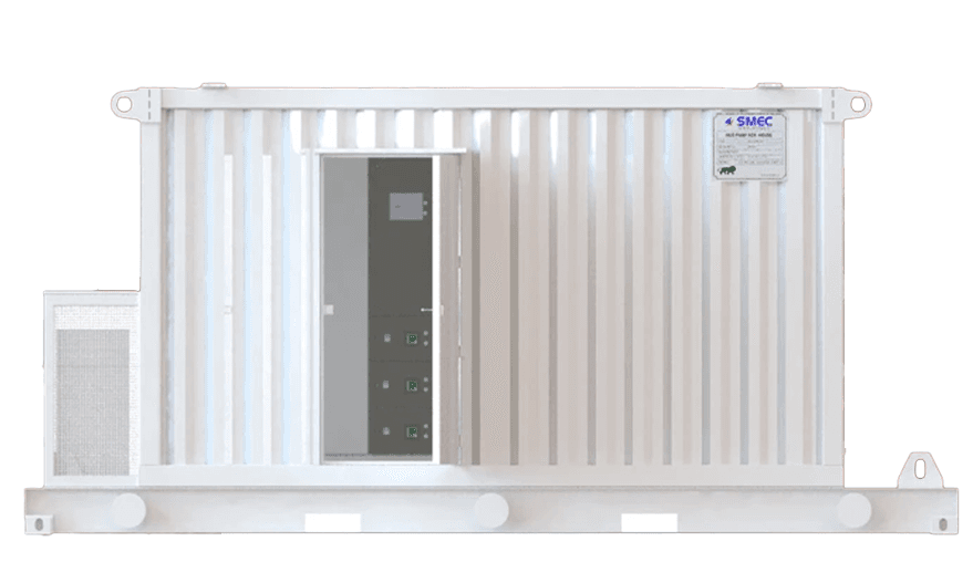 Power HousesPCR House | SCR House | VFD HouseKnow More
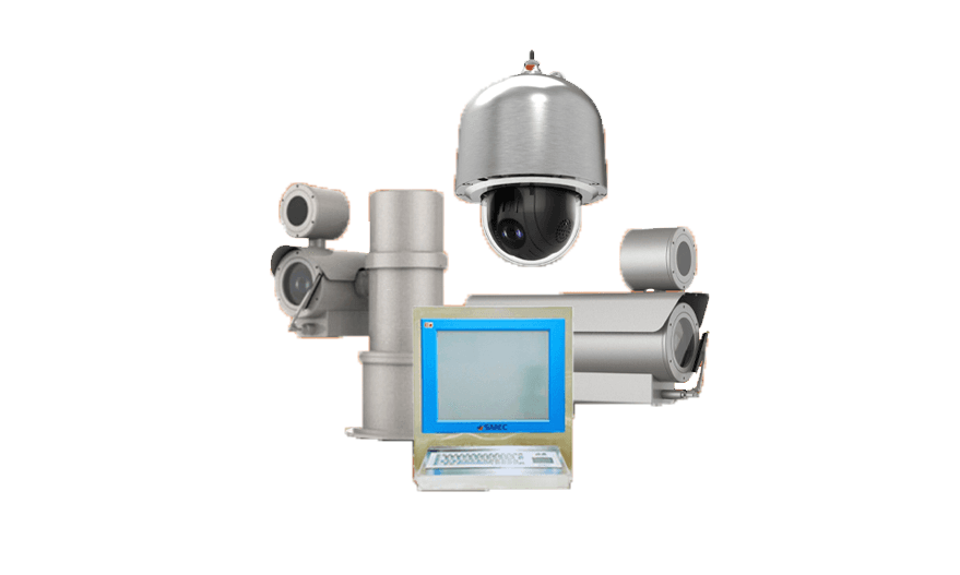 Advanced Perimeter Security SystemSecure Your Boundaries with SMEC's Advanced Perimeter Security System!Know More
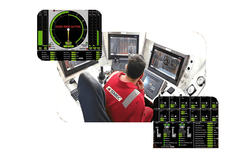 Drill Monitor SystemStay Alert, Stay Safe: Gas Watch Panel by SMECKnow More
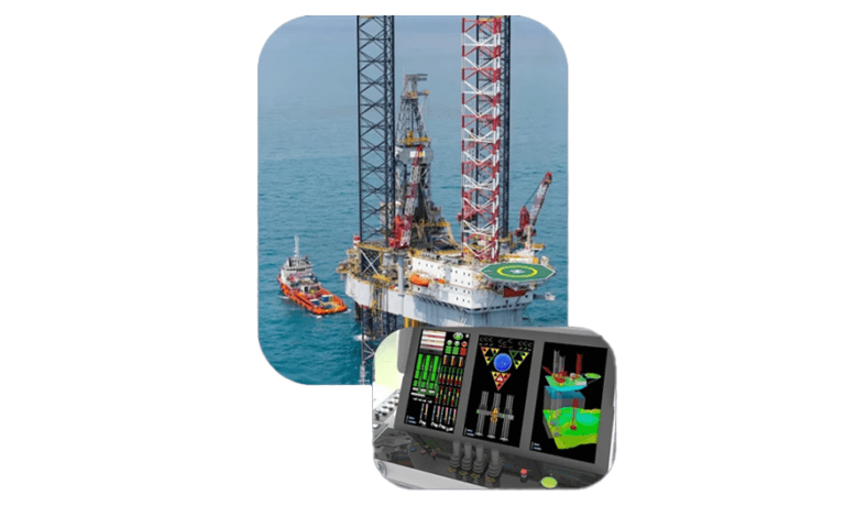 RPD System Jacking Control SystemPrecision Control for Unmatched Performance!Know More
Common questions
Can Integrated Drilling Control System be supplied for new build, retrofit or replacement?
The lifecycle route depends on the installed base, condition, interfaces, obsolescence and project requirements. SMEC can assess new-build, retrofit, repair or replacement scope where technically valid.
Can existing field wiring or interfaces be retained?
Possibly. Retention depends on survey findings, condition, ratings, compatibility, safety requirements, documentation and the cutover strategy.
What information is required for quotation?
Send the make/model or required specification, datasheets, drawings, ratings, interfaces, fault details where applicable, site location and required date or shutdown/mobilization window.
Does integrated drilling control replace every OEM controller?
Not necessarily; existing equipment controllers may be retained through verified interfaces.
What is required for an initial study?
Rig equipment list, existing control architecture, electrical drawings and operating sequences.
Related pages
Send the requirement
Send the available drawings, specification, make and model, site and required date. An engineer reviews the scope and replies.